

OpenSCAD Modules for Automatic Fillets (and Radii)
Fillets in OpenSCAD are not a straight forward endeavor. There have been many posts about the subject and many proposed solutions including libraries of generic fillet parts to be added to models. The fillet type that I have been experimenting with uses minkowski sums to achieve the task on a model of any geometry. Well, theoretically any model anyways. The use of two minkowski sums in the process makes the procedure unpractical for models of significant complexity because of the time required to produce the result. I do provide a partial solution to this limitation. My partial solution is to isolate an area of a larger model for local fillet generation. At the end of this BLOG post I provide a file containing modules for producing global or local fillets and radii within OpenSCAD. If you want to know more about the steps taken to generate the fillets continue reading otherwise you can jump to the end to download the SCAD file with the modules.
The following steps are performed automatically by the modules included in the file at the end of this post. These detailed steps and illustrations are provided for information purposes.
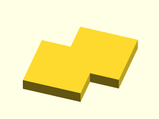
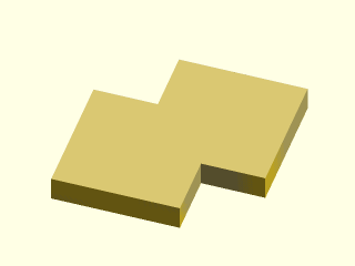
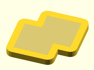
Original sample part: Here is our sample part, the second image shows the sample part with a transparent overlay of the sample part for reference. The transparent part overlay will be included in the following steps for a visual reference of the original shape.
STEP 1: Perform a minkowski sum of the sample part with a sphere (or cylinder if only rounding one axis of the part). (The image shows a slice of the minkowski sum for illustration purposes. The full minkowski sum completely encloses the sample part.)
STEP 2: Subtract the result from STEP 1 from a very large cube using a difference operation. The large cube needs to be larger than the object being worked on. This is analogous to inverting the normals on the model making a negative volume. (CGAL and OpenSCAD do not support negative volumes so this is a work around)
STEP 3: Perform a second Minkowski sum of the results from STEP 2 and the same sphere (or cylinder) used in STEP 1. NOTE: This is the most computationally intense step in the filleting process.
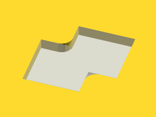
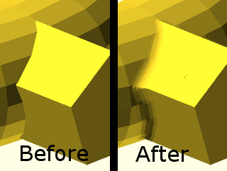
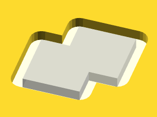
STEP 4: Perform a difference operation to subtract the result from STEP 3 from a large cube. The cube used in this step is slightly smaller than the cube used in STEP 2. The remaining object has internal fillets with a radius equal to the radius of the sphere (or cylinder) used in the previous steps. The top picture shows the object with the original shape shown transparent. The lower image has the transparent original shape removed.
This procedure works in the generalized 3D case with the size limitations I mentioned earlier. Additionally there is an analogous procedure to produce radii on external corners. Below are images of a sample three dimensional parts with fillets and radii generated automatically using the module file I provide below.
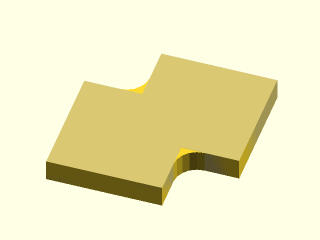
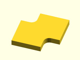
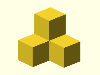
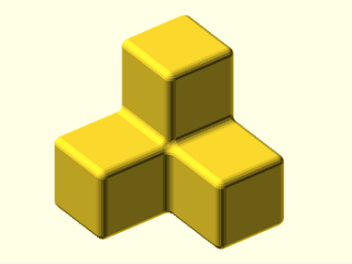
Base 3D part:
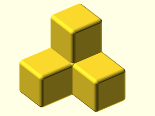
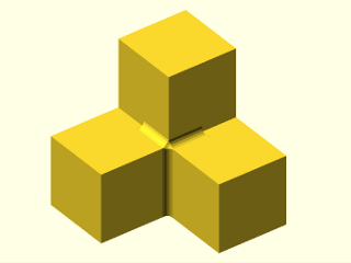
3D part with Fillets (31 minute build time):
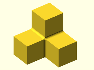
3D part with rounds (<1 minute build time):
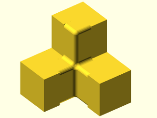
3D part with fillets and rounds (80 minute build time):
As I mentioned earlier there is a partial solution to the model size limitation of this procedure. This partial solution involves selecting a specific region of the model to be operated on and removing that region from the model while performing the operations. After the operations are complete the removed section of the model is inserted back into the larger model via a union command. This removal and re-installation of the sub-model is incorporated in the modules provided in the .scad file linked at the end of this BLOG post. To use the sub-modeling you just need to include a second object (child) in the module call to indicate the region to be operated on. For example using the SCAD file provided if the module add_fillets is called on an object alone all of the internal corners will be filleted
add_fillets(R=sample_R)
{
    sample_object();
}
If you call the add_fillets module and you include a second object only the areas of the first object that intersect the second object will be filleted. (in the example below the second object is a 10x10x10 cube.
add_fillets(R=sample_R)
{
    sample_object();
    cube([10,10,10])
}
Below are a couple of pictures of our sample object with localized region fillets and radii. All of the pictures below used a sphere with $fn=20 for the radius generation. The default in the module file provided is $fn=6 to ensure reasonable run times for the example object.
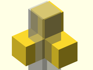
Local region illustrated by a transparent box:
3D part with local fillets:
3D part with local radii:

3D part with local fillets and radii:
Finally, below is the link to the the .scad file containing the modules for fillets and radii. The file also contains the simple examples shown in this post. In addition to generalized fillets and radii the modules can be used to do single axis fillets and radii. The single axis options (“x”,”y” and “z”) are much faster than the general option (“xzy”) so if you are only looking for a fillet in one axis it is better to use the specific axis you need. Play with the examples to see how each option works. The default “fn” value is 6 to keep the render time low. To get more usable results that number will need to be increased. (The sample images above used an fn=20).
Get the file here: fillets_and_rounds.scad