|
Input Field
|
Description
|
|
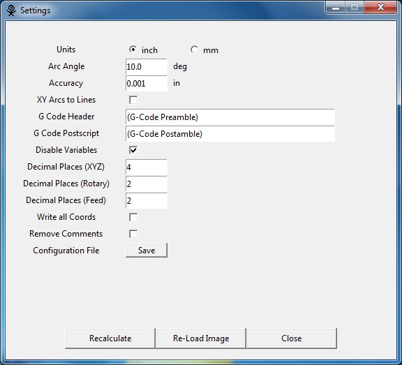
Units (inch/mm)
|
Set the units used by G-Code Ripper to inches or mm. This option affects the displayed units and the units output in the g-code.
|
|
Arc Angle
|
When arcs are converted to straight line segments the length of the line segments is controlled by this input parameter. The smaller the angle the more line segments are used to represent any given arc. If the arc angle is set to 1 deg 180 straight lines would represent a circle. At 10 degrees 18 arcs would represent a full circle.
|
|
Accuracy
|
This setting is used to determine when two points are in the same location.
|
|
XY Arcs to Lines
|
This option forces the conversion of all arcs to straight line segments prior to writing g-code output. This option is included for compatibility with some g-code interpreters.
|
|
G Code Header
|
The text that is entered in the G-Code header entry box is added to the beginning of the g-code commands in the G-Code Ripper output file. The commands are interpreted by the CNC machine as entered.
|
|
G Code Postscript
|
The text that is entered in the G-Code Postscript entry box is added to the end of the g-code commands in the G-Code Ripper output file. The commands are interpreted by the CNC machine as entered .
|
|
Disable Variables
|
Prevent the use of variables in the G-Code output. Variable are typically used for safe height and global feed rate.
|
|
Decimal Places XYZ
|
Number of decimal places to use for linear (x,y,z) coordinates when writing g-code output.
|
|
Decimal Places Rotary
|
Number of decimal places to use for rotary (a,b) coordinates when writing g-code output.
|
|
Decimal Places Feed
|
Number of decimal places to use for feed rates when writing g-code output.
|
|
Write All Coords
|
This option determines whether the output g-code writes all of the active axes on every g-code line or only the axes that have changed since the previous motion.
|
|
Remove Comments
|
Enabling this option causes G-Code Ripper to write output g-code files with none of the comments from the input g-code file. Otherwise the comments are simply passed through to the new g-code file.
|
|
Configuration File Save Button
|
Pressing the save button causes all of the current options to be saved to the default configuration file location. All of the settings in the current session will be recalled the next time G-Code Ripper is opened.
|