|
Input Field
|
Description
|
|
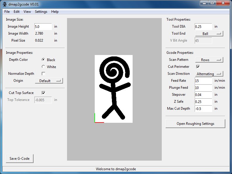
Image Height
|
The size of the G-Code output for the image in the Y direction (displayed as vertical on the screen) If cutting the full image the tool will move exactly the Image height in the Y direction. This means that if you are cutting with a flat cutter the actual cut size will be the Image height plus the diameter of the cutting tool.
|
|
Image Width
|
This dimension is automatically calculated and displayed to indicate the width or X axis size of the image G-Code output. This dimension is a function of the image aspect ratio and the "Image Height".
|
|
Pixel Size
|
This dimension is automatically calculated and displayed to indicate the resulting size of a single pixel based on the selected image and the "Image height" input.
|
|
Depth Color
|
The depth color setting determines whether the depth of cut is determined by the darkness (black) or lightness (white) of the image. If "black" is selected the portions of the image that are black will be the deepest cuts and white portions of the image will be at Z equals zero. Conversely if "white" is selected the white areas of the image will be cut the deepest.
|
|
Normalize Depth
|
Selecting this option tells the program to treat the darkest pixel as if it were black and the lightest pixel as if it were white. The remaining levels of grey between are stretched fill the range.
|
|
Origin
|
The origin determines the relative location of the g-code x and y zero location. The current location of the origin is displayed in the display window as a red and green lines. The red and green lines follow the RGB convention Red is the x-axis, Green in the y-axis.
|
|
Cut Top Surface
|
If "Cut Top Surface" is selected the whole image is cut even if the cut depth is zero. If this option is not selected the top surface is not cut. The tool path will move to Z-safe and rapid past the areas not cut.
|
|
Top Tolerance
|
The "Top Tolerance" determines how far a calculated cut has to be below the zero position before it is not considered a top surface cut.
|
|
Tool DIA
|
Specify the tool diameter.
|
|
Tool End
|
Specifies the tool shape (Ball End, Flat End, or V-Bit)
|
|
V Bit Angle
|
If the V-bit tool end option is selected this option determines the included angle of the V-bit.
|
|
Scan Pattern
|
This option determines if g-code is generated for the "Rows" (X direction), "Columns" (Y direction) or both "R then C" (Rows then Columns) or "C then R" (Columns then Rows).
|
|
Cut Perimeter
|
This option adds a perimeter cut to the g-code output when only "Rows" or only "Columns" is selected for the "Scan pattern". This can eliminate a scalloped look at the edge of an image.
|
|
Scan Direction
|
"Scan Direction" determines the cutting direction methodology.
Positive: Start milling at a low X or Y axis value, and move towards a high X or Y axis value
Negative: Start milling at a high X or Y axis value, and move towards a low X or Y axis value
Alternating: Start on the same end of the X or Y axis travel that the last move ended on. This reduces the amount of traverse movements
Up Milling: Start milling at low points, moving towards high points
Down Milling: Start milling at high points, moving towards low points
|
|
Feed Rate
|
Specify the tool feed rate that is output in the g-code output file.
|
|
Plunge Feed
|
Specify the tool feed rate that is output in the g-code output file when moving vertically into the material.
|
|
Stepover
|
The distance between adjacent rows or columns.
|
|
Z Safe
|
This is the z location that the tool will be directed to prior to any rapid movement.
|
|
Max Cut Depth
|
The depth of the deepest possible cut into the material.
|