F-Engrave V-Carve Calculations
Within F-engrave all parts of the font characters are
converted into short line segments. To determine the
toolpath for V-Carving we step along each line segment
that defines the text. (the size of the step is
adjustable in the V-Carve Settings). At each step along
each segment the maximum radius is determined. The max radius
circle always passes through the current step point and is
centered on a the Y-axis of the local coordinate system.
The local coordinate system is centered on the current
step point and the Y-axis is generally perpendicular to
the line segment. At sharp turns from segment to segment
the local coordinate system is stepped between the
current line segment and the next line segment to avoid
cutting the corner.
The calculation is dependant on the font being defined by
loops that are created CW (clockwise). Internal
loops are defined CCW (counter clockwise). If this
convention is reversed the flip normals option in
F-Engrave will correct the calculation.
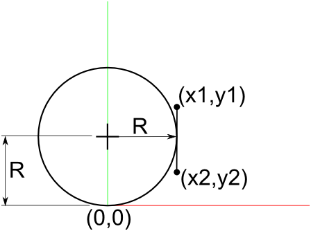
Figure 1
We start with a couple of special cases. The first special
case is x1==x2. If x1==x2 (Figure 1) the line segment
is vertical in the local coordinate system. For this
case we simply set R to X1 (or X2) and check to make
sure the line segment exists at y=R. If the line segment
exists at y=R we save the Radius R. If all of the line
segment is above or below y=R the result is discarded.
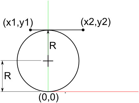
Figure 2
The second special case is y1==y2. If y1==y2 (Figure 2)
the line segment is horizontal in the local coordinate
system. For this case we check to make sure y1 (or y2)>0.
If y1 is >0 we set R to y1*1/2. We also check to make sure
the line segment exists at the x=0. If the line segment
exists at x=0 we save the Radius R. If not the result
is discarded.
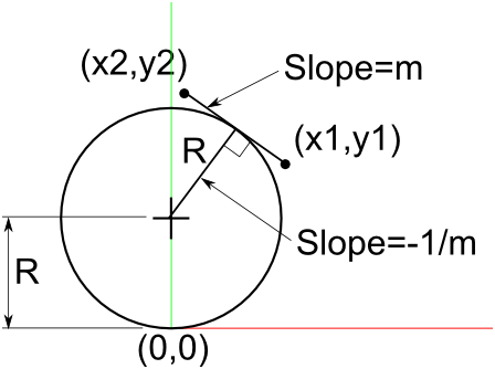
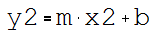
Figure 3
Next we move to a more general case. This case is a line segment
with a arbitrary slope (Figure 3). This case requires a bit of
algebra. we start by looking at the geometry and set up a few
governing equations. First we need the equation of a line that
passes through the two points in the line segment (eq1).
(eq1)
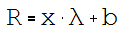
The second equation is the equation for a line that passes though
the center of our circle and is perpendicular to the first line. The
first line has a slope of m. To make the second line perpendicular
to the first line we set it's slope to -1/m. Since we know the slope
and we know the line passes through the y-axis at R (y-intercept)
we can write the equation for the second line as (eq2).
(eq2)
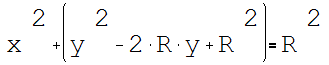
The third and last governing equation (eq3) is the equation for
a line circle with radius R centered at x=0, y=R. (Figure 3.)
(eq3)
Combining (eq1) and (eq2):
Solve for R:
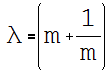
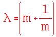
Create a new variable Lambda to
make the equations less messy:
(eq4)
(eq5)
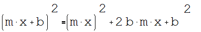
Expand (eq3):
Cancel out the squared R values and
Substitute for R and y using (eq1)
and (eq5)
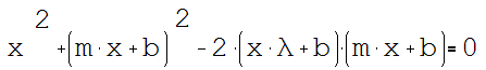
The first term is simply:
Expanding the second term:
Expanding the third term:
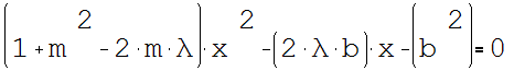
All three terms together expands to:
After combining the b squared terms, canceling
out the 2bmx terms and grouping we get (eq6) which
is in the form of the quadratic equation:
(the equations in red below are used in the
F-Engrave python file)
(eq6)
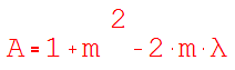
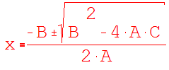
Quadratic
Equation:
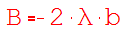
Where:
(eq4)
m = Slope of the line segment
and
b = Y intercept of line passing through the line
segment points
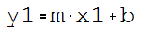
We know the two end points of the line segment so we
can determine the equation of a line passing through
those two point (x1,y1) and (x2,y2) using (eq1)
(eq1)
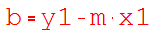
Substitute the 1st point coordinates into (eq1):
Solve for b:
(eq7)
Substitute the 1st point coordinates into (eq1):
(eq8)
Substitute the equation solved for b into (eq8)
and solve for m:
(eq9)
Similar to the first two special cases we need to check if
the line segment exists at the intersection point and save
the Radius R if it does. We do this by checking
that min(x1,x2) < x < max(x1,x2).
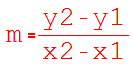
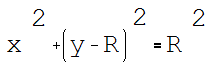
Figure 5
Figure 4
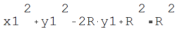
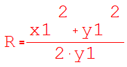
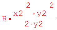
The last two cases are when the line segment end points limit
the size of the max circle (Figure 4 and Figure 5). For this
case (eq3) from above is used again. This equation is performed
for both point (x1,y1) and (x2,y2).
(eq3)
And for (x2,y2):
After these calculations are performed for every segment
the minimum R value has been determined and its center and
radius are saved for generating the tool path. The Radius
determines the depth of the cut as a function of the
v-cutter angle and max diameter.