Contents

Top
Tips from Scorch
Questions and Answers
Command Line Options
Keyboard Shortcuts
Mouse Bindings
Configuration File
Main Window Settings
General Settings
V-Carve Settings
PBM Settings

F-Engrave Manual

F-Engrave Home Download Scorch Works Home

Questions and Answers

How do I get the ttf2cxf_stream program to work?

F-Engrave launches the ttf2cxf_stream program behind the scenes. To use a true type font file (TTF) you need to put the .ttf file you want to use in the fonts directory (or the directory pointed to in the setting dialog). The TTF files should show up in the list of available fonts if the ttf2cxf_stream program is operating correctly and it is located in the same folder as the f-engrave program. If the ttf2cxf_stream program is not present or not working you should get a message in the console window stating that ttf2cxf is not working. More setup info is here:
F-Engrave Setup

Command Line Options

Usage python f-engrave-XX.py [-g file | -f fontdir ]
or
f-engrave-XX.exe [-g file | -f fontdir ]
-g
(or --gcode_file)
f-engrave g-code output file to read. Reading the settings from previously saved g-code files only works if the "Suppress Comments" option was not selected in the "General settings" when the g-code file was saved. The default is to suppress the comments because a lot of people are using GRBL these days and GRBL does not handle comments well.
-f
(or --fontdir)
path to font file directory
-h
(or --help)
print syntax help to console window.
Example
(Using python script with
preinstalled python distribution)
python f-engrave-XX.py -g my_file.ngc -f /my_font_dir/sub_dir
Example
(Using precompiled
Windows executable)
f-engrave-XX.exe -g my_file.ngc -f C:/My_font_dir/sub_dir

Keyboard Shortcuts

F1 Open the Help dialog box. (There is nothing in the help except a reference back to the web page and my e-mail address)
F2 Opens General Settings Dialog Box
F3 Opens V-Carve Setting Dialog Box
F4 Opens PBM Setting Dialog Box
F5 Recalculate (This performs the same functions as the recalculate button on the main page)
Control-Up Arrow Scroll Font List Box (Operating system dependant)
Control-Down Arrow Scroll Font List Box (Operating system dependant)
Page Up Zoom in on the center of the display window.
Page Down Zoom out from the center of the display window.

Mouse Bindings

Left Mouse Button Zoom in and out. Hold the left mouse button down and move the mouse up or down.
Right Mouse Button Pan. Hold the right mouse button down and move the mouse.
Mouse Scroll Wheel Depending on the operating system this may scroll the font list box.

Configuration File

config.ngc
or
.fengraverc
When F-Engrave starts up it looks for a file named "config.ngc". If the file is found it is read and all of the F-Engrave options are set according to the settings saved in the config file. F-Engrave looks for the config file in the current directory and in the users home directory (the default save directory). The config file can be named "connfig.ngc" or ".fengraverc" if either of these are found it will be used to set the default settings. Only the first config file found is read.

To create a config file with your preferred options for startup just open F-Engrave and change the settings to your liking and save a configuration file by using the "Configuration File" "Save" button in the general settings window. (If you are not using the precompiled windows executable you could also just edit the settings in the .py file)

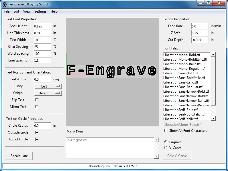
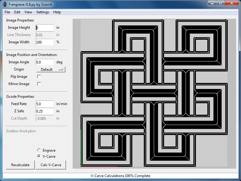
Main Window (Text Mode and Image Mode)

F-Engrave - Text Mode F-Engrave - Image Mode

Input Field Description
Text Height
or
Image Height
Character height of a single line of text. This setting also controls the height image files (DXF or PBM) that are imported. (F-Engrave treats the DXF file data as a character)
Line Thickness Thickness or width of lines used when displaying text. To preview what engraved text this should be set equal to the diameter of the cut that will be made on the CNC machine.

When the V-Carve option is selected this does not have any effect on the displayed line thickness.
Text Width
or
Image Width
The width of characters or image (DXF or PBM) file data. When 100% is selected the width of the character is not scaled. Value other than 100% will result in the character width scaled by the percentage specified. (i.e. Circles will become ovals)
Char Spacing The space between characters F-Engrave uses constant character spacing. The space between all characters are the same. The character spacing is determined as a percentage of the maximum width of the characters in the currently selected font. 0% will result in the characters touching each other and can be useful in special cases.
Word Spacing The space between word or the width of the space character. This is determined as a percentage of the maximum width of the characters in the currently selected font.
Line Spacing The vertical spacing between lines of text. This is a multiple of the text height previously input. A vertical spacing of 1.0 could result in consecutive lines of text touching each other if the maximum height character is directly below a character that extends the lowest (like a "g").
Text Angle
or
Image Angle
Rotation of the text or image (DXF or PBM) from horizontal.
Justify Justification lines up the Left, Right or Center of multiple lines of text. This option has no effect on a single line of text.
Origin The origin determines the relative location of the g-code x and y zero location. The current location of the origin is displayed in the display window as a red and green lines. The red and green lines follow the RGB convention Red is the x-axis, Green in the y-axis.

The default location of the origin is the zero position of the first character. When using the text on circle options the default origin position will change to the center of the circle which the text is being placed on.
Flip Text
or
Flip Image
Flip the text or image about a horizontal axis. (This is the same a Mirror Text except is it about the horizontal axis)
Mirror Text
or
Mirror Image
Mirror the text or image about a vertical axis (This is the same as Flip Text except is it about the vertical axis)
Circle Radius The circle radius is the radius of the circle that the text in the input box is placed on. If the circle radius is set to 0.0 the text is not placed on a circle.
Outside Circle Select whether the text is placed so that is falls on the inside of the circle radius or the outside of the circle radius.
Top of Circle Select whether the text is placed on the top of the circle of on the bottom of the circle (concave up or concave down). If the text angle is set to something other than 0.0 the top and bottom of the circle will be rotated by the angle specified in the text angle input box.
Feed Rate Specify the tool feed rate that is output in the g-code output file.
Z Safe This is the z location that the tool will be directed to prior to any rapid moved.
Cut Depth Simply the depth of the engraving cut. This setting has no effect when the v-carve option is selected.
Font Files This list box shows the file names for the font files (CXF and TTF). The current font directory can be changed in the settings dialog.
Show All Font Characters This option temporarily shows all of the font characters available in the currently selected font file.
Engrave/V-Carve Select whether the program is in "Engrave" or "V-Carve" mode this setting.
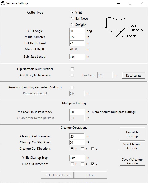
Calculate V-Carve This button executes the V-Carving feature of the program. Executing this command can result in long calculation times.
Recalculate Recalculate the display for all of the settings to preview the result. Everything is recalculated by this command except the V-Carve calculation.
Input Text This is the text that will be displayed in the preview box and eventually exported to g-code.
Status Bar The status bar provides various bits of information when working with F-Engrave. One of the most useful is the bounding box size. When the recalculate button is pressed the overall size of the engraving or v-carving will be calculated and displayed in the status bar in terms of a bounding box size with a width and height. This is very useful if you have a fixed area in which to engrave.

General Settings


Input Field Description
Units (inch/mm) Set the units used by F-Engrave to inches or mm. This option affects the displayed units and the units output in the g-code.
X Offset and Y Offset On the main input window the "origin" setting determines the location of the g-code x and y zero location relative to the text or DXF design. The "X Offset" and "Y Offset" values are additional modifications to the zero location. The offsets are added to the g-code output values for x and y. That is if the text is centered around x=0,y=0 and the X Offset=3.0 and Y Offset=4.0 the text would then be centered around x=3.0,y=4.0.
Arc Angle All arcs, circles and splines are reduced to individual straight line segments by F-Engrave. The "Arc Angle" determines how many line segments are used to describe these curved entities. If the "Arc Angle" is set to 90 degrees a circle would be represented by a square (90 deg corners). If the angle is set to 60 degrees a circle would be represented by a hexagon. The lower the angle the more accurate the representation (at the cost of computing time and potentially CNC performance)
Accuracy
(New in version 0.5)
The accuracy setting determines the maximum distance between two points that are considered coincident. This is setting can be increased to reduce unnecessary Z moves when the end point of one line and the start point of the next line are very close but they are not coincident. This setting also reduced the sensitivity to DXF splines with loops at sharp corners that would cause bad v-carve paths (I will eventually add an example of this here)
G Code Header The text that is entered in the G-Code header entry box is added to the beginning of the g-code commands in the F-Engrave output file. The commands are interpreted by the CNC machine as entered. The default values (G17 G90 G64 M3 S3000 M7) are explained below:
G17
Sets XY plane
G90
Fixed cycle, simple cycle, for roughing (Z-axis emphasis)
G64 P0.003
G64 P- (motion blending tolerance set to 0.003) This is the default in the legacy program "engrave.py"
G64
G64 without P option keeps the best speed possible, no matter how far away from the programmed point you end up.
M3 S3000
Spindle start at 3000
M7
Turn mist coolant on (if it is available)
G Code Postscript The text that is entered in the G-Code Postscript entry box is added to the end of the g-code commands in the F-Engrave output file. The commands are interpreted by the CNC machine as entered . The default values (M5 M9 M2) are explained below:
M5
Stop Spindle
M9
Turn all coolant off
M2
End Program
Font Directory The directory which F-Engrave will search for font files (TTF and CXF) and drawing exchange files (DXF) files. The files in the searched directory that have the correct extensions are displayed in the Font Files list box. Opening a DXF file using the menus will automatically change the current font directory to the directory containing the DXF file that was opened.
Height Calculation
Max Used/Max All
The height of the text can be determined one of two ways. The first is the maximum height of the characters used in the input box. In this case the maximum height of the characters in the input box is used to determine the height of the characters.

The second option is "Max All" when this is selected the maximum height of all of the characters available in the font file is used to determine the height of the text. When "Max All" is used it is possible to have an output text height less than the height input in the main window because the character with the max height may not be used in the engraved text.
Add Box/Circle This option adds a box around the output text. If the text placed on a circle a bounding circle is added in lieu of a bounding box.
Border Gap (multiple of line thickness) The Border gap determines the size of the bounding box added by the "Add Box/Circle" option. The gap between the text and the bounding box is set in units of length (in or mm). This input has changed in version 0.8 but when reading old .ngc files F-Engrave will calculate the equivalent entry for the new format (i.e. version 0.8 is backward compatible with .ngc files created in previous versions of F-Engrave)

V-Carve Settings


Input Field Description
V-Bit Angle The angle of the v-cutting bit that will be used.
Apparently the actual angle on bits may not match the angle specified by the manufacturer.
V-Bit Diameter The maximum diameter of a cut that will be generated.
This can be set lower than the actual bit diameter to control the max width/depth of cut.
Cut Depth Limit This sets the maximum depth of v-carve cut. If 0 is entered in this field the cut depth will default to the depth required to plunge the v-bit up to the v-bit diameter. For Straight cutters the default is 1/2 the bit diameter.
Max Cut Depth The calculated maximum depth of cut that will be generated. This is calculated based on the Cut Depth Limit entry value and the cutter geometry. (See the description for Cut Depth Limit for additional information)
Sub-Step Length The v-carving algorithm steps along the font or DXF outline and performs tool location and depth calculations at a fixed interval. The fixed interval is the "Sub-Step Length" a large substep length will increase the speed of the v-carve calculation but could result in a more faceted looking v-carve. Reducing the "Sub-Step Length" too much can cause excessive calculation time and reduced CNC machine performance (due to excessive short G1 commands). If in doubt start with a larger step size and reduce the value until the results seem reasonable.
Flip Normals
(V-Carve Side)
F-Engrave assumes that the font or image (DXF) file creates closed paths running clockwise around the shape to be carved and defaults to carving the internal space of the character. The flip normals reverses the processing of the character or DXF shape. This results in the outside of the character or DXF shape being removed.
Plot During V-Carve Calculation Enable or disable plotting of the v-carve calculation progress during the v-carve calculation. This option will increase the speed of the calculation process without affecting the g-code output.
Finish Pass Stock
and
Max Depth per Pass
The Finish Pass Stock is the amount (depth) of material that will be left for the final pass of cutting. F-Engrave will always leave the Finish Pass Stock to be removed during the final pass even if your Max Depth per Pass is set to a value deeper than the max depth of cut for a given design.

If your settings are:
Finish Pass Stock =.03
Max Depth per Pass = -.1

And your max depth at a location in the design is .5 the the cut depths for the passes at that location in the design will be.
pass 1: .1
pass 2: .2
pass 3: .3
pass 4: .4
pass 5: .47
pass 6: .5 (this is the finish pass. .5-.47=.03)
Cleanup Cut Diameter This sets the diameter of the cleanup bit. Simply set this to the diameter of the cleanup bit that will be used.
Cleanup Cut Step Over This is the step over for the cleanup cuts. This number is entered as a percentage of the cleanup bit diameter.
Cleanup Cut Directions These check boxes determine what type of tool paths are used with the cleanup bit.
P: Cut the perimeter of the area to be cleaned up X: Cut in the X direction Y: Cut in the Y direction
V-Bit Cleanup Step This is the step over to be used when cleaning up areas that cannot be reached with the cleanup bit. The cutting is to be performed using the same V-bit that was used for cutting the main v-carve design. This step over is entered as the step distance in the currently selected length units.
V-Bit Cut Directions These check boxes determine what type of tool paths are used with the V-bit.
P: Cut the perimeter of the area to be cleaned up X: Cut in the X direction Y: Cut in the Y direction
Button:
Calculate Cleanup
Calculate the area that requires cleanup. After the area is determined the cut paths for cleaning up the design are calculated based on the parameters set below. The area calculation will only be performed one time after the v-carve calculation is completed. F-Engrave will remember the previous area results and use them until a new v-carve calculation is performed.
Button:
Save Cleanup G-Code
This button saves the cleanup G-Code to a file.
Button:
Save Cleanup G-Code
This button saves the v-bit cleanup G-Code to a file.

PBM Settings


Input Field Description
(These option are direct inputs to Potrace. For more information refer to the Potrace documentation)
Turn Policy Tells Potrace how to resolve ambiguities in path decomposition.
Turd Size Suppress speckles of up to this size
Alpha Max Corner threshold parameter
Long Curve Turn on/off curve optimization. Curve optimization reduces the time required to perform the v-carve calculations.
Opt Tolerance Curve optimization tolerance

Known Issues

- F-Engrave outputs a G1 command for every calculated step when performing v-carving. If the step size is set small the CNC machine will never reach the input feed rate if it cannot accelerate to the input speed over the step length.

- Not all DXF files are supported. There are a lot of different entity types in DXF files not all of them are supported.

- Not all TTF files are supported. Some TTF files have embedded images instead of vector graphic representations the TTF fonts with embedded images are not supported.

Scorch Works Home
Scorch Works Home