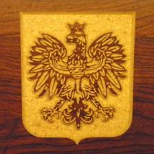
V-Carving Tutorial
(V-Carve Almost Anything Using F-Engrave Image Mode)
To successfully use this tutorial F-Engrave and Potrace need to be installed and working. Help installing these programs is available at: F-Engrave Setup
Step 1. Select an
image to v-carve.
Any image that is black and white or that you can convert to black and white.
Step 2. Convert the
image to a format that F-Engrave can import.
Assuming Potrace is installed and working properly the image types that can be imported are: BMP (Windows Bitmap), PBM (Portable Bitmap), PGM (Portable Graymap) and PPM (Portable Pixmap).
The input image should be converted to black and white using any image editing software. If pixel values other than black and white appear in the input, they will be converted to black and white within F-Engrave (Potrace actually does the work). Color or grayscale picture will produce a result but the internal conversion does not allow you to preview the true input. (additionally, the size of true black and white images is dramatically smaller than grayscale and color images.)
Step 3. Import the
image into F-Engrave
3a. Open F-Engrave
- Windows: Double click the f-engrave.exe file.
- Linux: Type python f-engrave-xx.py at a command prompt. (where xx is the version number)
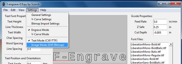
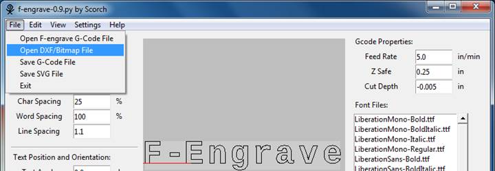
3b. Change the mode to image [ Settings - Image Mode ]
3b.
![]()
3c. Open your image file by selecting [ File - Open DXF/Bitmap File ] then use the file open dialog to navigate to and select an image file.
3c.
![]()
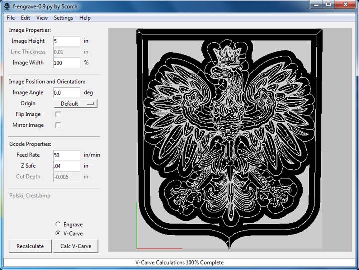
Step 4. Change the
main window settings to set the output size and cut method.
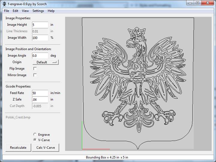
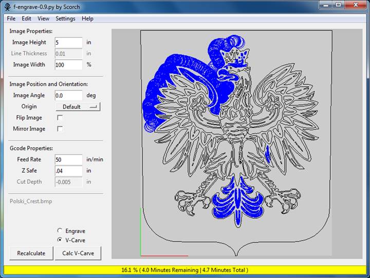
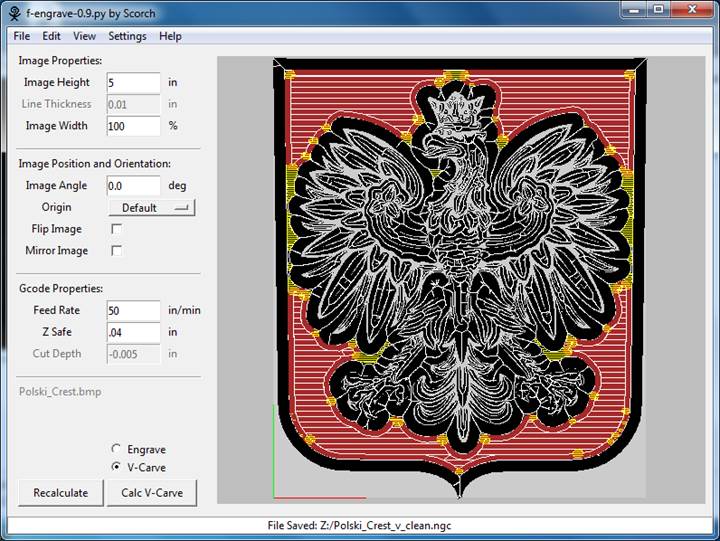
4a. Adjust the size of the image. This is accomplished by changing the Image height property. The resulting image size is displayed in the status bar.
4b. Change the Feed Rate and Z Safe values to values that are suitable for your machine and material. The defaults are pretty safe for most operations (when using English units) increasing the Feed Rate and decreasing the Z Safe can help improve the speed of the carving process. (for V-Carving the Cut Depth is determined by the v-bit geometry, which will be set later, so there is no need to change this value unless you are using engrave mode)
4c. Since we will be v-carving, select V-Carve mode at the bottom of the window.
4d. The Origin option can be modified to change the zero position of the g-code output if desired. The current position of the origin is displayed on the preview window by red and blue lines (shown in the lower left in the image below).
4e. After changing settings on the main screen click the Recalculate button to update the display.
4e. 4b. 4c. 4a. 4d.
![]()
![]()
![]()
![]()
Step 5. Change the
V-Carve Settings
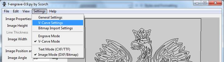
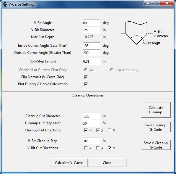
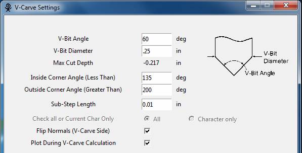
5a. Open the V-Carve Settings window [ Settings - V-Carve Settings ]
5a.
![]()
5b. Set the V-Bit Angle and V-Bit Diameter to match your cutting bit. The V-Bit Diameter can be set to diameters less than the actual cutting bit diameter to limit the depth of v-carving.
5b. 6a.![]()
Step 6. Execute
V-Carve Calculation
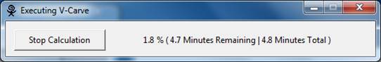
6a. All of the necessary settings have been changed. Executed the V-Carve calculation by clicking the Calculate V-Carve button on the v-carve settings window.
As the calculation is performed the display will update and a status window will give an estimate of the time remaining. When the calculation is complete the blue areas will be replaced by black and the tool paths will be shown as white lines. This process can take a long time for complex designs.
Step 7. Review the
Results
The areas that will be touched by the v-bit are shown in black and the tool paths are shown in white. As seen in the screenshot some areas of the image have not been carved. These regions can be cleaned up using the cleanup section of the V-Carve Settings window.
Step 8. Clean Up
Settings
8a. Enter the cleanup cut data:
Cleanup Cut Diameter: Diameter of the cleanup bit to be used. (typically, a straight flat nosed bit)
Cleanup Cut Step Over: Step over distance for the cleanup cuts. Entered as a percentage of the bit diameter
Cleanup Cut Directions: The cut direction to use for the cleanup bit, "X" lines in the x-direction, "Y" lines in the y-direction, "P" cut the perimeter of the uncut area.
8b. Enter the v-bit cleanup cut data:
V-bit cleanup is cutting the tight corners that the cleanup bit cannot reach. The v-bit specified for v-carving is used for this operation.
Cleanup Cut Step Over: Step over distance for the cleanup cuts. Entered as a distance.
Cleanup Cut Directions: The cut direction to use for the v-bit cleanup, "X" lines in the x-direction, "Y" lines in the y-direction, "P" cut the perimeter of the uncut area.
9a. 8b. 8a.

Step 9. Clean Up
Execution and Save
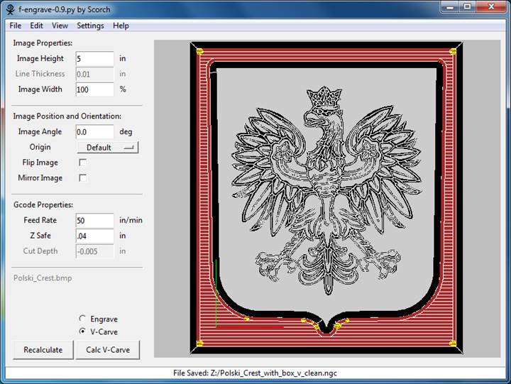
9a. The cleanup calculation can now be executed using the Calculate Cleanup button on the v-carve settings window. The first time this button is pressed after a v-carve operation the cleanup areas are calculated. The areas are saved and reused until the Calculate V-Carve button is press again. After the cleanup calculations are complete the display will be updated. The cleanup cut area will be plotted as reddish/brown areas with white tool path lines and the v-bit tool path will be plotted as yellow lines.
The cleanup g-code and the v-bit cleanup g-code can now be saved using the buttons on the v-carve settings window. Each of the two cleanup operations should be saved to separate files. (Don't forget to save the v-carving g-code file from the main window file menu)
The saved g-code files can now be run on a CNC machine. The output from F-Engrave is compatible with LinuxCNC and Mach3.
Extra Credit
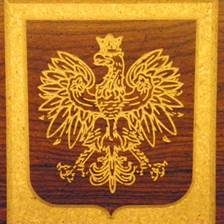
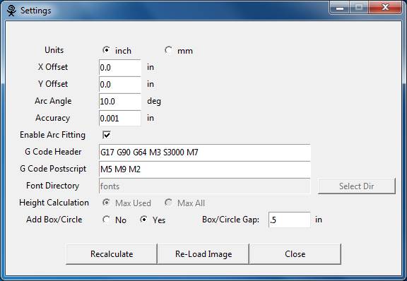
To make the second carving shown at the beginning of this document two settings need to be adjusted. First the normals of the image need to be flipped (in the v-carve settings window). This changes the side of the image that gets carved so that the white gets carve instead of the black in the image. Second a bounding box is added to the image to limit the amount of material that is removed around the image (in the general settings window). A screenshot after all of the calculations are performed for this case is shown below (next page). See if you can do similar with your image.
![]()
Additional notes
Looking closely at the images on the first page reveals that some detail is missing from the carving. In the left image detail is missing from the eagle’s face. The image on the right is clearly missing detail from the eagles feet. The g-code output included these details but the v-bit used to carve the images did not come to a true point. The diameter of the tip is 0.040 inches so any features less than 0.040 inches in the output design will be lost because the bit is cutting air.
Good Luck!
Scorch