Somewhere along the line the flower broke off of the solar wobbler that we had lying around the house. When it broke I shoved it in a drawer...
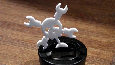
Always Working on Something


Somewhere along the line the flower broke off of the solar wobbler that we had lying around the house. When it broke I shoved it in a drawer...
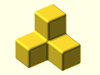
Fillets in OpenSCAD are not a straight forward endeavor. There have been many posts about the subject and many proposed solutions including...