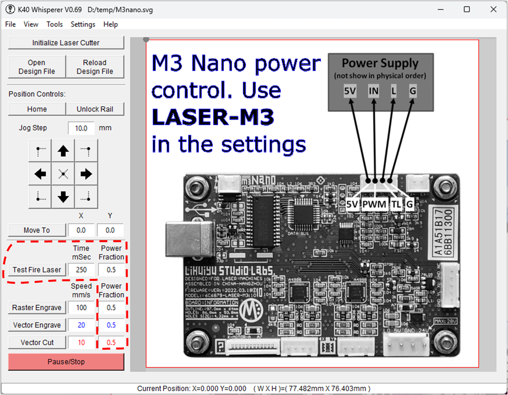
There are new laser machines being shipped (from Vevor) without potentiometer power control or digital power control on the laser engraving...
Always Working on Something


There are new laser machines being shipped (from Vevor) without potentiometer power control or digital power control on the laser engraving...
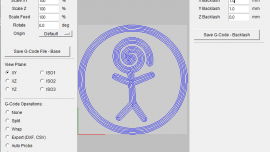
I recently released G-Code Ripper Version 0.23 which includes the ability to do basic backlash compensation on a g-code file. The new version van...
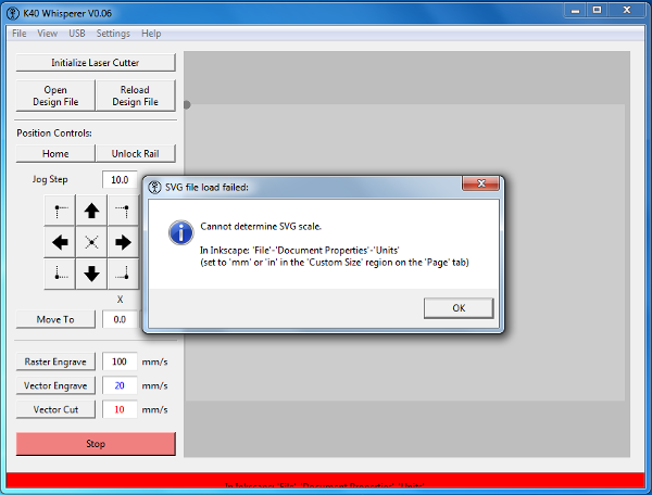
K40 Whisperer is a bit finicky about the SVG files that it will accept. If you are importing files from sources other than a recent version of...
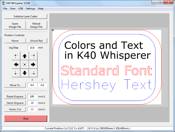
In K40 Whisperer the red and blue vector paths in SVG files are converted to vector cut and vector engrave paths respectively. A few people have...
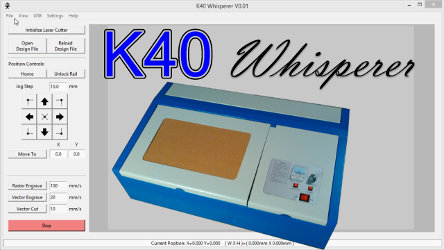
After months of reverse engineering I am happy to announce that the initial version of K40 Whisperer is available for download under the GPL...

A couple of months ago I wrote an Inkscape extension that allows users to save LYZ files that are compatible with Laser Draw (LaserDRW). Laser Draw...
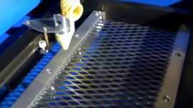
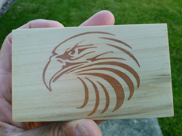
I built a spring loaded platform for my K40 laser. The purpose of the platform is to allow for the use of different thicknesses of material while...
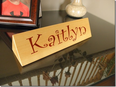
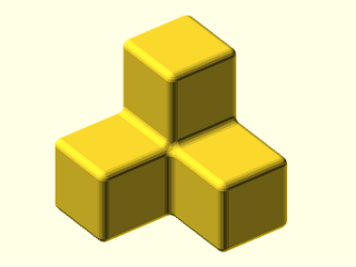
I made a three sided nameplate for my goddaughter Kaitlyn’s 1st birthday. The main body is basswood and “Kaitlyn” is inlayed on each side of the...
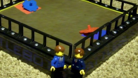
I made a mold for injection molding Makey Robot spinning tops a few weeks ago. The tops are designed to be giveaway items at Maker Faire Milwaukee...
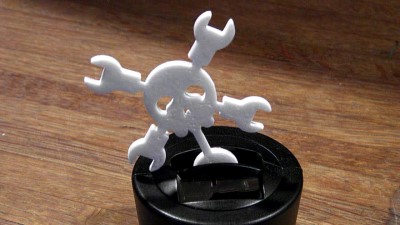
Somewhere along the line the flower broke off of the solar wobbler that we had lying around the house. When it broke I shoved it in a drawer...
I made the majority of this homemade EDM a long time ago. Recently I have been finishing this project by making a better structure for the linear...
In the past week I have updated ScorchCAD a couple of times. The first update helped verify that the autocomplete function in the ScorchCAD Editor...
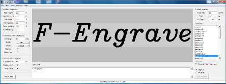
F-Engrave v1.56 is out with some bug fixes and better line/arc fitting. There was a huge bug in the old curve fitting which caused the "M" in...
Fillets in OpenSCAD are not a straight forward endeavor. There have been many posts about the subject and many proposed solutions including...
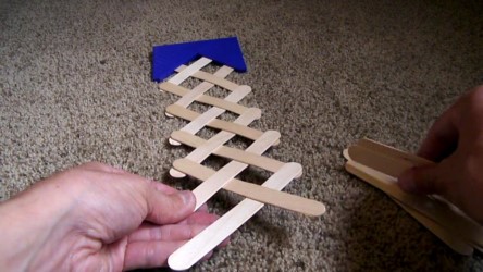
I made a quick little 3D printable fixture to aid in the construction of stick bombs. The type of bomb this fixture makes is my favorite. If the...
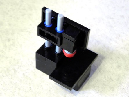
My two boys love having a 3D printer in the house. I have made a variety of items for them. My 9 year old, Derek, came up with a great little...
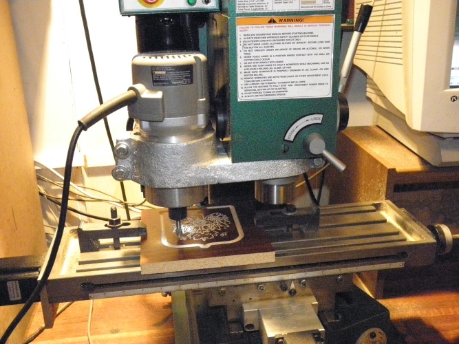
Halloween is approaching so I thought I would share the Jack-o-lantern that I made for Halloween last year (2014). I carved an image, lithophane...
F-Engrave 1.50 has been released and is now available on the F-Engrave page. Here are a few of the highlights from this release: Modified...
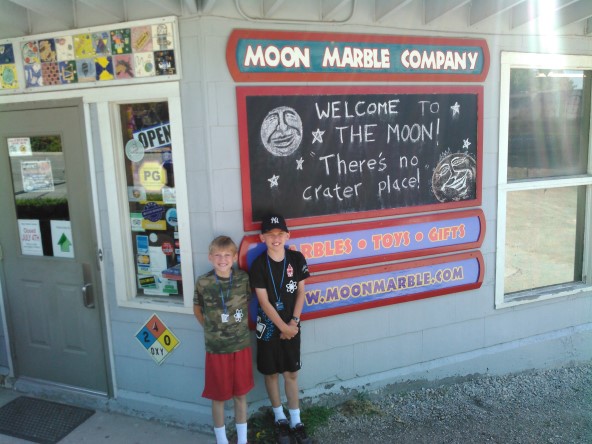
This year I took my two boys to the Kansas City Maker Faire for the second year in a row. We once again had a great time. This year we attended...
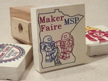
We are continuing the tradition of custom Maker Faire hitch covers for our Maker Faire road trips. Since the Minneapolis St. Paul Mini Maker...
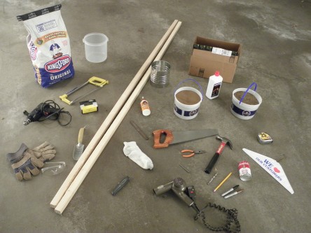
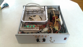
As a challenge to myself I decided to make a very simple foundry setup for melting and casting aluminum. I have a larger more involved equipment...
I find myself doing CNC work on wood about half of the time so I thought it would be nice to have a high speed spindle. I decided to mount my...
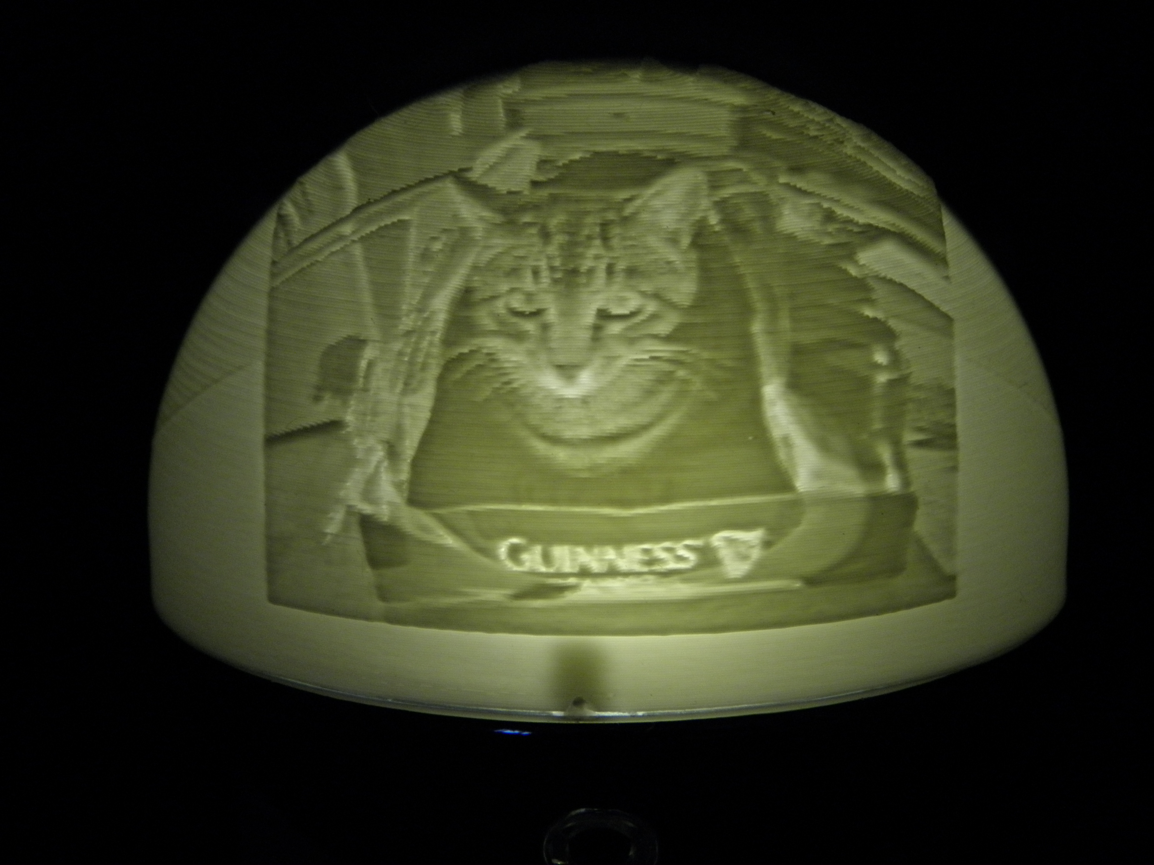
Ever since I first saw a lithophane in a YouTube video I have thought they were really cool. I have made cylindrical lithophanes previously with my...
The call for makers for the first Minneapolis/St. Paul Mini Maker Faire is now open. I thought I would throw my hat into the ring to present a few...
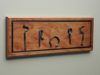
This is a collection of bottle openers that I made from 16D common nails. Some of them work better than others but I tried to incorporate a...
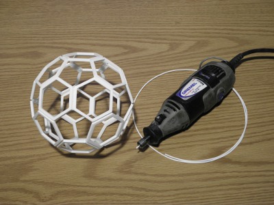
A couple of years ago Fran posted a really interesting video demonstrating friction welding. Fran used a cheap harbor freight rotary tool and...
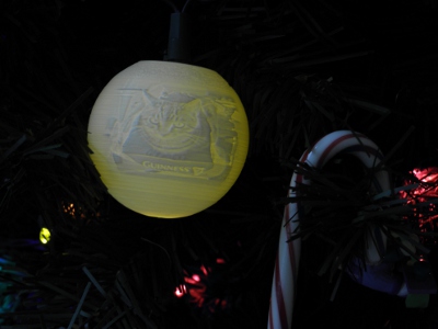
I have been playing with making spherical lithophanes with my new 3D printer (PrintrBot Simple Metal). I wrote some Java code to read the image...
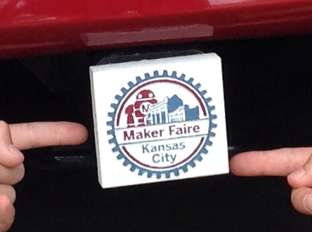
When my kids and I went to Maker Faire Kansas City we made a Maker Faire themed cover for the hitch receiver on our minivan. For Kansas City we...
After a summer break from ScorchCAD development I am back at it. The latest version of ScorchCAD is available on Google Play. ScorchCAD is...
I released a new version of the image to g-code conversion program Dmap2Gcode. The new version is 0.02, the updates to the program are listed...