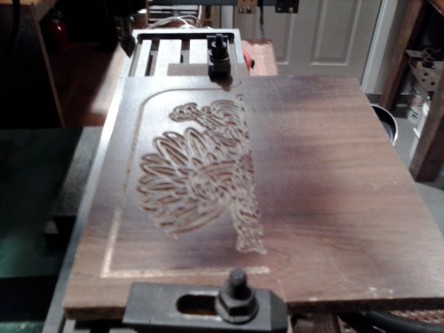
The latest version of F-Engrave includes major improvements to the v-carve calculation speed. The first is based on input from geo01005. He...
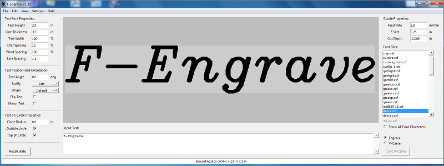
Always Working on Something


The latest version of F-Engrave includes major improvements to the v-carve calculation speed. The first is based on input from geo01005. He...
When g-code is generated by most software it is assumed that the stock material is flat and level. Sometimes the stock material is warped, not...
I released a new version of F-Engrave with minor fix to better v-carve imported DXF files with small imperfections. F-Engrave V1.37.
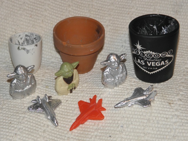
I have been sporadically experimenting with my electric micro foundry setup for almost a year. Recently I have been trying different...
Over the Memorial Day weekend I made this newton's cradle for my kids. I used some 5/8 inch ball bearings I had left over from another...

I thought it would be interesting to see how well a simple hot glue gun with standard hot glue could produce injection molded parts. Although...

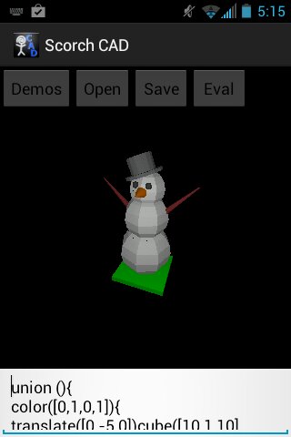
ScorchCAD (A clone of OpenSCAD for Android devices) is now available on Google Play: ScorchCAD. There is also a new ScorchCAD webpage here:...
This is my second short update of my progress on ScorchCAD (A clone of OpenSCAD for Android devices). I am slowly adding more features and...
I have had some feedback from ShapeOko users indicating that there are some issues using the default F-Engrave output with GRBL. I thought I...
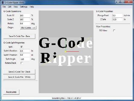
G-Code Ripper Version 0.05 is now available. The new version can export tool paths read from a g-code file to a DXF or CSV (Comma Separated...
This is a quick update of my progress on ScorchCAD (A clone of OpenSCAD for Android devices). I am slowly adding features. So far I these...
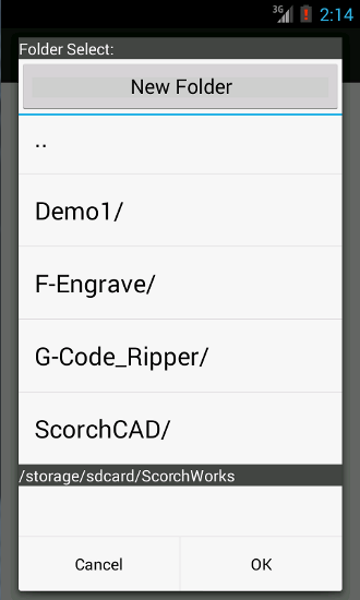
Since there isn't a built in file dialog interface for android development I have been searching for one that I could use without starting from...
I uploaded version 1.33 of F-Engrave, it is available on my web page. (F-Engrave 1.33) Changes in Version 1.33: - Added option for scaling...
Hack a Day is having another contest. This time it is a microcontroller based contest. The entries need to hide hackaday.com in a...
F-Engrave Version 1.32 is now available on the F-Engrave Web Page. This release includes a few minor items that I have had backlogged for a...
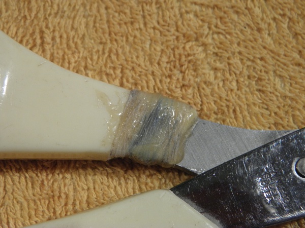
Sometimes a broken part was generally too weak to begin with or does not have much surface area for bonding. To achieve a good repair additional...

ScorchCAD is a side project that I have worked on for a while. It is a clone of OpenSCAD written for Android devices. It is a clone of...
I made a quick release of F-Engrave Version 1.31 to fix a new bug that was preventing batch mode from working in version 1.30. I have a backlog of...

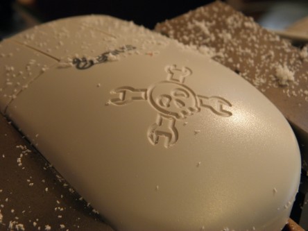
Hackaday is having a contest to see where people can put the Hackaday skull and wrenches logo. I thought I would take a little time and throw...
G-Code Ripper 0.04 has been released with a fix for a bug that can occur when reading arc segments (G3,G3). The new version also allows zero...
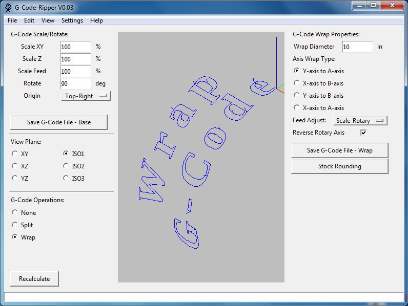
G-Code Ripper version 0.03 has been posted to the G-Code Ripper Homepage. The new version has more plotting options including more isometric...
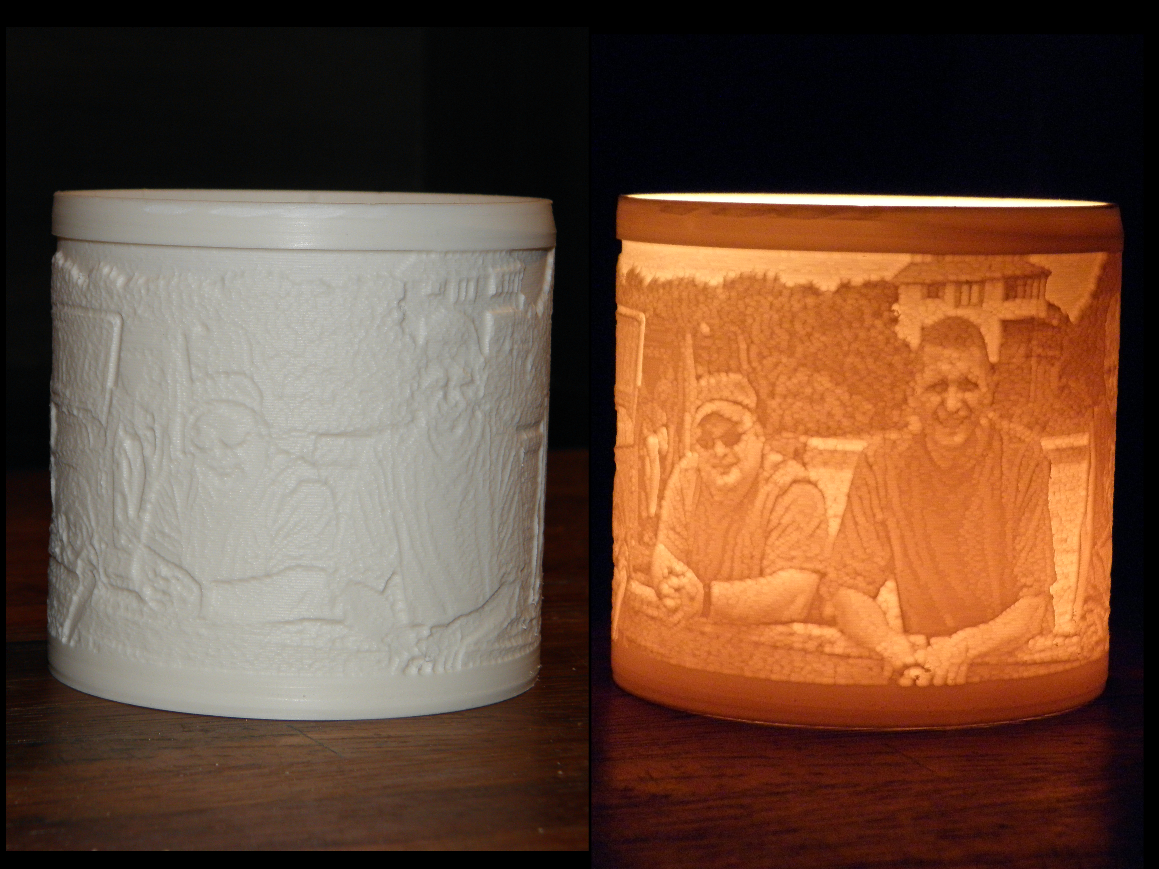
I saw a video of a cylindrical lithophane made from a PVC pipe a few years back (You tube Link). I had always wanted to replicate it. Not only...
F-Engrave now can determine which side of the loops in a DXF design need to be cut. Previously the input needed to be formatted so that the...
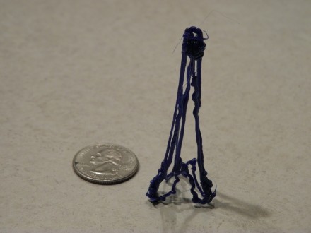
I had a chance to sit down for a couple of minutes with a 3Doodler. In just a minute or two I made the little tripod tower in the picture. It...
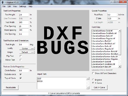
F-Engrave V1.22 is now available. This version fixed a few DXF import bugs and a v-carve cleanup bug. I also changed the lower limit on the...
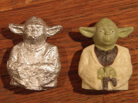
I have been working on making a very small electric furnace for doing small aluminum castings. As part of testing an early iteration of the...
Version 1.21 of F-Engrave is now available. More command line options have been added. A new batch mode (-b,--batch) that skips the GUI. ...
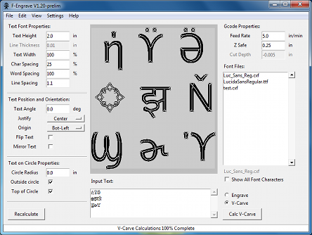
F-Engrave 1.20 with extended character support is now available for download. To enable extended characters in F-Engrave there is a new setting...
I have uploaded the first version of G-Code Ripper (formerly referred to as the g-code splitting program). G-Code Ripper can read g-code files...
I have been making progress on the g-code splitting program (yet to be named). I think I have all of feature for the initial release, including...